

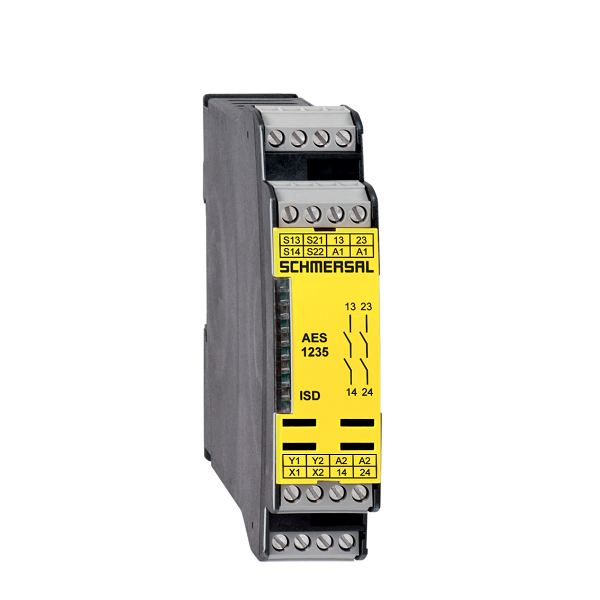
Estimated Lead Time : 3-5 Weeks
Manufacturer : Schmersal
AES 1265
Ordering data
Product type description : AES 1265
Article number (order number) : 101170051
EAN (European Article Number) : 4030661297132
eCl@ss number, version 12.0 : 27-37-18-19
eCl@ss number, version 11.0 : 27-37-18-19
eCl@ss number, version 9.0 : 27-37-18-19
ETIM number, version 7.0 : EC001449
ETIM number, version 6.0 : EC001449
Available until : 31.12.2023
Approvals – Standards
Certificates : BG, cULus
General data
Standards :
BG-GS-ET-14, BG-GS-ET-20, EN IEC 62061, EN ISO 13849-1, EN IEC 60947-5-1
EN IEC 60947-5-3, EN IEC 60947-5-5, EN IEC 60204-1, EN IEC 60947-1
Climatic stress : EN 60068-2-3, BG-GS-ET-14
Enclosure material : Glass-fibre reinforced thermoplastic, ventilated
Gross weight : 174 g
General data – Features
Stop-Category : 0
Wire breakage detection : Yes
Cross-circuit detection : Yes
Feedback circuit : Yes
Automatic reset function : Yes
Reset after disconnection of supply voltage : Yes
Earth connection detection : Yes
Integral system diagnostics, status : Yes
Number of LEDs : 1
Number of normally closed (NC) : 2
Number of normally open (NO) : 2
Number of undelayed semi-conductor outputs with signaling function : 2
Number of safety contacts : 2
Number of signalling outputs : 2
Safety classification
Standards : EN ISO 13849-1, EN IEC 61508
Safety classification – Relay outputs
Performance Level, up to : d
Category : 3
PFH value : 1.00 x 10?7 /h
Notice : for max. 50,000 switching cycles/year and max. 80% contact load
Safety Integrity Level (SIL), suitable for applications in : 2
Mission time : 20 Year(s)
Mechanical data
Mechanical life, minimum : 20,000,000 Operations
Mounting : Snaps onto standard DIN rail to EN 60715
Mechanical data – Connection technique
Terminal designations : IEC/EN 60947-1
Termination : rigid or flexible, Screw terminals M20 x 1.5
Cable section, minimum : 0.25 mm²
Cable section, maximum : 2.5 mm²
Tightening torque of Clips : 0.6 Nm
Mechanical data – Dimensions
Width : 22.5 mm
Height : 100 mm
Depth : 121 mm
Ambient conditions
Degree of protection of the enclosure : IP40
Degree of protection of the mounting space : IP54
Degree of protection of clips or terminals : IP20
Ambient temperature : +0 … +55 °C
Storage and transport temperature, minimum : -25 °C
Storage and transport temperature, maximum : +70 °C
Resistance to vibrations : 10…55 Hz, Amplitude 0.35 mm, ± 15 %
Restistance to shock : 30 g / 11 ms
Ambient conditions – Insulation values
Rated impulse withstand voltage Uimp : 4 kV
Overvoltage category : III
Degree of pollution : 2
Electrical data
Frequency range : 50 Hz, 60 Hz
Operating voltage : 24 VAC -15 % / +10 %, 24 VDC -10 % / +20 %
Ripple voltage : 10 %
Thermal test current : 6 A
Rated operating voltage : 24 VAC
Rated operating voltage : 24 VDC
Rated AC voltage for controls, 50 Hz, minimum : 20.4 VAC
Rated control voltage at AC 50 Hz, maximum : 26.4 VAC
Rated AC voltage for controls, 60 Hz, minimum : 20.4 VAC
Rated control voltage at AC 60 Hz, maximum : 26.4 VAC
Rated AC voltage for controls at DC minimum : 20.4 VDC
Rated control voltage at DC, maximum : 28.8 VDC
Electrical power consumption : 5 W
Contact resistance, maximum : 0.1 Ω
Note (Contact resistance) : in new state
Drop-out delay in case of power failure, typically : 80 ms
Drop-out delay in case of emergency, typically : 20 ms
Pull-in delay at automatic start, maximum, typically : 100 ms
Pull-in delay at RESET, typically : 20 ms
Material of the contacts, electrical : Ag-Ni 10 and 0.2 µm gold-plated
Electrical data – Safe relay outputs
Voltage, Utilisation category AC-15 : 230 VAC
Current, Utilisation category AC-15 : 6 A
Voltage, Utilisation category DC-13 : 24 VDC
Current, Utilisation category DC-13 : 6 A
Switching capacity, minimum : 10 VDC
Switching capacity, minimum : 10 mA
Switching capacity, maximum : 250 VAC
Switching capacity, maximum : 8 A
Electrical data – Digital inputs
Input signal, HIGH Signal “1” : 10 … 30 VDC
Input signal, LOW Signal “0” : 0 … 2 VDC
Conduction resistance, maximum : 40 Ω
Electrical data – Digital Output
Voltage, Utilisation category DC-12 : 24 VDC
Current, Utilisation category DC-12 : 0.1 A
Electrical data – Relay outputs (auxiliary contacts)
Switching capacity, maximum : 24 VDC
Switching capacity, maximum : 2 A
Electrical data – Electromagnetic compatibility (EMC)
EMC rating : EMC-Directive
Integral system diagnosis (ISD)
Note (ISD -Faults) : The following faults are registered by the safety monitoring modules and indicated by ISD.
Faults :
Failure of the safety relay to pull-in or drop-out
Failure of door contacts to open or close
Cross-wire or short-circuit monitoring of the switch connections
Interruption of the switch connections
Fault on the input circuits or the relay control circuits of the safety monitoring module
Other data
Note (applications) : Safety sensor, Guard system
Note
Note (General) :
Inductive loads (e.g. contactors, relays, etc.) are to be suppressed by means of a suitable circuit.
Wiring example
Note (Wiring diagram)
The wiring diagram is shown with guard doors closed and in de-energised condition.
To secure a guard door up to PL d and Category 3
Monitoring 1 guard door(s), each with a magnetic safety sensor of the BNS range
The ISD tables (Intergral System Diagnostics) for analysis of the fault indications and their causes are shown in the appendix.
Expansion of enable delay time: The enable delay time can be increased from 0.1 s to 1 s by changing the position of a jumper link connection under the cover of the unit.
The feedback circuit monitors the position of the contactors K3 and K4.
Start push button: A start push button (NO) can optionally be connected into the feedback circuit. With the guard door closed, the enabling paths are then not closed until the start push button has been operated.
If only one external relay or contactor is used to switch the load, the system can be classified in Control Category 3 to ISO 13849-1, if exclusion of the fault “Failure of the external contactor” can be substantiated and is documented, e.g. by using a reliable down-rated contactor. A second contactor leads to an increase in the level of security by redundant switching to switch the load off.
If neither start button nor feedback circuit are connected, a jumper connection must be mounted between X1 and A1.
Modification for 2 NC contacts: The safety monitoring module can be modified to monitor two NC contacts by bridging the terminals A1 and X2. In this configuration, the short-circuit detection becomes inoperative.
Shipping Weight : 0.174 Kg



Reviews
There are no reviews yet.