Estimated Lead Time : 3-5 Weeks
Manufacturer : Schmersal
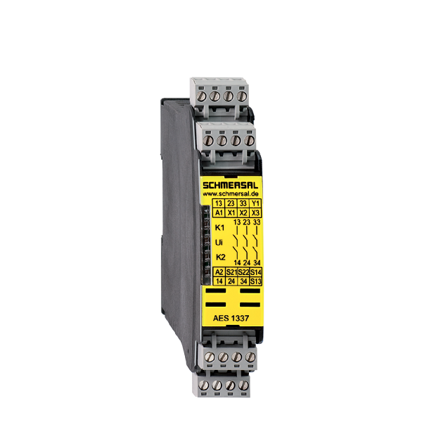
AES1337
Ordering data
Note (Delivery capacity) : Phased-out product
Product type description : AES1337
Article number (order number) : 101172210
EAN (European Article Number) : 4250116201839
eCl@ss number, version 12.0 : 27-37-18-19
eCl@ss number, version 11.0 : 27-37-18-19
eCl@ss number, version 9.0 : 27-37-18-19
ETIM number, version 7.0 : EC001449
ETIM number, version 6.0 : EC001449
Available until : 31.12.2023
Approvals – Standards
Certificates : BG, cULus, CCC
General data
Standards :
BG-GS-ET-14, EN IEC 62061, EN ISO 13849-1, EN IEC 60947-5-1, EN IEC 60947-5-3
EN IEC 60947-5-5, EN IEC 61508, EN IEC 60204-1, EN IEC 60947-1
Climatic stress : EN 60068-2-78
Enclosure material : Glass-fibre reinforced thermoplastic, ventilated
Gross weight : 280 g
General data – Features
Stop-Category : 0
Wire breakage detection : Yes
Cross-circuit detection : Yes
Feedback circuit : Yes
Automatic reset function : Yes
Reset after disconnection of supply voltage : Yes
Earth connection detection : Yes
Integral system diagnostics, status : Yes
Number of auxiliary contacts : 1
Number of LEDs : 4
Number of normally closed (NC) : 1
Number of normally open (NO) : 1
Number of safety contacts : 3
Safety classification
Performance Level, up to : e
Category : 4
Diagnostic Coverage (DC) Level : ≥ 99 %
PFH value : 2.00 x 10?8 /h
Safety Integrity Level (SIL), suitable for applications in : 3
Mission time : 20 Year(s)
Common Cause Failure (CCF), minimum : 65
Mechanical data
Mechanical life, minimum : 10,000,000 Operations
Mounting : Snaps onto standard DIN rail to EN 60715
Mechanical data – Connection technique
Terminal designations : IEC/EN 60947-1
Termination : rigid or flexible, Screw terminals M20 x 1.5
Cable section, minimum : 0.25 mm²
Cable section, maximum : 2.5 mm²
Tightening torque of Clips : 0.6 Nm
Mechanical data – Dimensions
Width : 22.5 mm
Height : 100 mm
Depth : 121 mm
Ambient conditions
Degree of protection of the enclosure : IP40
Degree of protection of the mounting space : IP54
Degree of protection of clips or terminals : IP20
Ambient temperature : -25 … +45 °C
Storage and transport temperature, minimum : -40 °C
Storage and transport temperature, maximum : +85 °C
Resistance to vibrations : 10 … 55 Hz, Amplitude 0.35 mm
Restistance to shock : 10 g / 11 ms
Ambient conditions – Insulation values
Overvoltage category : III
Degree of pollution : 2
Electrical data
Frequency range : 50 Hz, 60 Hz
Thermal test current : 6 A
Rated AC voltage for controls, 50 Hz, minimum : 20.4 VAC
Rated control voltage at AC 50 Hz, maximum : 26.4 VAC
Rated AC voltage for controls, 60 Hz, minimum : 20.4 VAC
Rated control voltage at AC 60 Hz, maximum : 26.4 VAC
Rated AC voltage for controls at DC minimum : 20.4 VDC
Rated control voltage at DC, maximum : 28.8 VDC
Electrical power consumption : 2.1 W
Electrical power consumption : 3.5 VA
Contact resistance, maximum : 0.1 Ω
Note (Contact resistance) : in new state
Drop-out delay in case of power failure, typically : 80 ms
Drop-out delay in case of emergency, typically : 20 ms
Pull-in delay at automatic start, maximum, typically : 100 ms
Pull-in delay at RESET, typically : 20 ms
Material of the contacts, electrical : AgSn0. self-cleaning, positive drive
Electrical data – Safe relay outputs
Voltage, Utilisation category AC-15 : 230 VAC
Current, Utilisation category AC-15 : 6 A
Voltage, Utilisation category DC-13 : 24 VDC
Current, Utilisation category DC-13 : 6 A
Switching capacity, minimum : 10 VDC
Switching capacity, minimum : 10 mA
Switching capacity, maximum : 250 VAC
Switching capacity, maximum : 8 A
Electrical data – Digital inputs
Conduction resistance, maximum : 40 Ω
Electrical data – Relay outputs (auxiliary contacts)
Switching capacity, maximum : 24 VDC
Switching capacity, maximum : 2 A
Electrical data – Electromagnetic compatibility (EMC)
EMC rating : EMC-Directive
Status indication
Indicated operating states
Position relay K2
Position relay K1
Internal operating voltage Ui
Other data
Note (applications) : Safety sensor, Guard system
Note
Note (General) :
Inductive loads (e.g. contactors, relays, etc.) are to be suppressed by means of a suitable circuit.
Wiring example
Note (Wiring diagram)
The wiring diagram is shown with guard doors closed and in de-energised condition.
To secure a guard door up to PL d and Category 3
Monitoring 1 guard door(s), each with a magnetic safety sensor of the BNS range.
The feedback circuit monitors the position of the contactors K3 and K4.
To secure a guard door up to PL e and Category 4.
Automatic start: The automatic start is programmed by connecting the feedback circuit to the terminals X1/X3. If the feedback circuit is not required, establish a bridge.
Start button (S) with edge detection
Shipping Weight : 0.174 Kg


Reviews
There are no reviews yet.